-
Mohammed Omer authoredMohammed Omer authored

- Desktop 3D Printer
- Popular Open Source/Kit 3D Printers
- Choosing a 3D Printer for the OLSK
- 3D Printer Design Goals:
- Technical Specifications
- Further Requirements (For Workshops)
- Design Categories
- Current 3D Printer Design Log
- Frame
- Mechanics
- CAD 3D Model
- Linear Bearings on Smooth rods Comparison
- X-carriage Design
- Lubricating linear bearings
- Belts and Pulleys
- Electronics
- Configuring the MKS Sbase V1.3
- Direct Drive vs Bowden Drive
- Z-axis design for lifting Build Platform
- Calculating travel on Z - axis
- All Metal Hotend vs PTFE Lined Hotend
- Comparison of three popular Nozzles
- Heated Bed Choice
- Mains voltage AC bed heater
- Low voltage (12V or 24V) DC bed heater
- Choosing Power Supply
- 3D printer Wiring
- 3D Printer Wiring Connectors
- Optional Features (Future Work)
- Configuring Marlin for MKS Sbase v1.3
- Defining Motherboard type
- Setting Stepper Steps
- Configuring Extruder Steps
- Configuring NPN NO 12mm inductive probe
- Wiring a mechanical EndStop
- Connecting LEDs
- Setting motor current in Marlin
- Initial Bed Levelling, First Layer Thickness and Z-Offset
- Sending print commands
- Setting up MKS TFT32 Display
- Calibration & Fine Tuning Methods
- Problems and Fixes
- Next Improvements
- Build Instructions
- Fabrication
- Pre-Assembly
- Final Assembly
Desktop 3D Printer
Popular Open Source/Kit 3D Printers
Preliminary research was carried out to see which open source designs and commercial 3D printers are popular in the 3D printer community. These will be used as a starting point for the development of the desktop 3D Printer. Various repositories such as Youtube, Github, Instructables, GrabCad, Thingiverse, Personal Blogs and Technical Forums were searched.
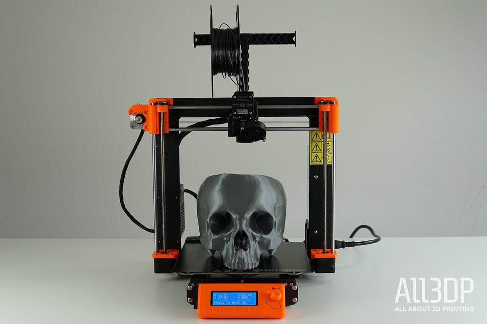
- The Prusa i3MK3 is one of the most popular open source 3D printers which consistently ranks among the best printers money can buy. The printer currently costs about 800 Euros. However since many parts have to still be bought from Prusa, it isn't an ideal choice for people living outside Europe or in developing countries. Again, since pone buys a kit, there is not much the user can choose from.
- The Vulcaman V1 Reprap 3D-Printer with a build cost of 300€ is a CoreXY fully DIY 3D printer based on the reprap model. It has a fully enclosed design and the design is licensed under Attribution-NonCommercial-ShareAlike 4.0 International (CC BY-NC-SA 4.0)
- BOM, CAD and a detailed instruction manual are available.
- Much interaction from community on the design and 15+ rebuilds which shows the design is relatively simple with good instructions and is reproducible.
- The shape is an a boxed construction which lends to its rigidity and it is also enclosed.
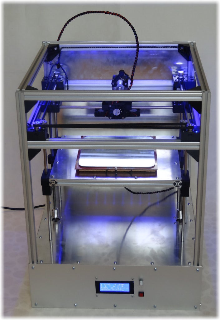
Specifications:- Dimensions: 44cm x 44cm x 60cm
- Build Volume: 20cm x 20cm X 26cm
- Travel Speed: 300mm/s
- Resolution: up to 0.05mm
- Electronic: Ramps 1.4 with TMC2100 1/256 microstep Motordriver
- The Falla 3D is an OpenSource 3D Printer with a magnetic levitation system for the bearings of the X and Y axes. The printer is also modular (it can extrude all 3mm and 1.75 mm filaments) and is scalable.
- BOM and CAD files exist on github
- Specifications:
- Scalable up to a 90x60x60 cm printing area (Printer size 100x70x70 cm)
- Double Extruder - With a single FUM hotend, with a classic double 3mm hotend or with a 1.75 Bowden system.
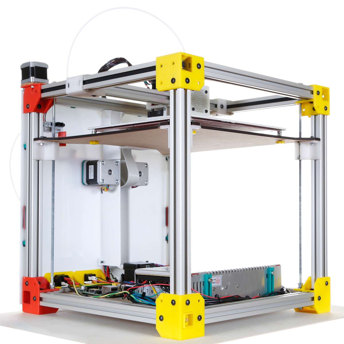
- The D-bot Core XY 3D printer from user Spauda01 on Makerbot's Thingiverse is another solid aluminium frame design with a coreXY mechanism. The design has high community interaction and over 140 replications.
- BOM, CAD and Build instructins (video and pdf guide) available
- Costs about 550$

- Build Volume: 300mm x 200mm x 325mm
- Licences under Attribution-ShareAlike 3.0 Unported (CC BY-SA 3.0) i.e. commercial as well.
- Voron v2.4 by Paul Nokel is a high end DIY 3D Printer that is fully open source and is popular for having excellent print quality and speed along with intuitive assembly documentation. The Voron 2.1 uses mains current to heat the stationary bed, and 12v everywhere else. The printer is however on the expensive side of DIY prinitng and is realtively complicated for someone new in 3D printing. Here is also a Voron buildlog.
-
Hypercube 3D Printer is a rigid boxed shape 3D printer made from 2020 aluminium extrusion profiles from user Tech2C and is very popular on the thingiverse website. The design also employs the coreXY mechanism with the attempt to reduce the X-carriage weight. The printer however has a cantilevered bed which causes Z-wobble in prints mainly noticed in printers that have tried to scale the design to a larger build volume.
-
Hypercube Evolution (also known as the HEVO), developed by SCOTT_3D, is an iteration or remix of the HyperCube 3D printer designed by Tech2C. It adds 3030 extrusions around the frame for added thickness, as well as a few more upgrades. It has a decent Wiki as well as a couple of different BOM generators, online and in Excel format. The design comes with configurable CAD files for required build volume and single or double Z axis motors. The build is relatively simple and allows modifications. The design is fully open source i.e. users can use the design, modify it and also use it for commercial purposes. The design is very popular in the community, since it improves on the previous design by tech2C by making it more rigid.

- HEVO build guide from a german maker detailing his build and sourcing of parts
- Fusion360 Model from user1
- Fuson360 Model from User2
- Hypercube Evolution Oliver RT or HevORT is a remix high end DIY 3D Printer based on the Hypercube Evolution design which can cost about 2000 USD. The printer has auto-levelling of bed using 3 extra z-axis motors. It has a rigid Gantry for achieving high accelerations and speed using a direct drive extruder, whereby the user has achieved a build speed of 500mm/s+ with the printer.
- Github repository and website has printer configurator, BOM generator and fusion 360 CAD model.
Some Commercial and semi open Source (DIY) Desktop Printers
- Stratasys (Industrial Higher End)
- Ultimaker (Mid consumer however still expensive) - These are considered highly reliable, however come at a high price tag starting at 2500 Euros for the base model
- Creality Ender 3 - Cheapest available chinese printer (about 200 Euros) that is also open source. Provides great quality prints and is also certified by OSHWA to be fully open source. However, only this model from Crealty.
There are many cheap 3D printer kits that are available these days like the Creality or Tronxy models. These work and do the job but the parts are not optimum or quality components. More often than not users upgrade their cheap printers and end up spending twice as much in the end by replacing components. It is preferrable then to build your own printer from scratch where you get to decide what components you would like to have in the printer. Also if something breaks, you know exactly what to do or how to fix it. Lastly, it is a great learning experience. Moreover, if the build instructions and CAD model are available the user could also customize the build to adapt to locally available raw materials.
Great general information and guidelines on building a DIY 3D printer - https://hackaday.com/2016/07/06/build-a-3d-printer-workhorse/
Choosing a 3D Printer for the OLSK
The aim of the Open Lab 3D printer is to develop a DIY 3D Printer design that is robust and reliable. It should be possible for anyone to build it, with the posssibility of modifying it according to their budget, requirements and available resources.
Requirements:
- The Open lab 3D Printer must be a reliable machine with quality components that can be built from scratch with having to source as few components as possible.
- The printer can be built locally without having to purchase an expensive Kit or fully assembled 3D Printer.
- The printer should make it possible for users to choose their own components for key elements depending on local availability of components and budget.
With quality components and systems being more expensive, 3 designs categories are proposed depending on the user budget. These are namely a high end model, a mid-consumer model and a budget model.
Using MoSCoW method of prioritization to prioritize the design objectives.
- Must have (M) — these are critical and must be included into the product. If even one isn’t included, the release is considered a failure. These can be downgraded if there’s agreement among stakeholders.
- Should have (S) — these requirements are important but not crucial for the release. They’re the first level of “Nice to have”, and generally share the importance of MUST requirements, without being so time-sensitive.
- Could have (C) — these requirements are desirable but not necessary for the release. They’re usually low-cost enhancements to the product. Due to their lower importance, they’re the second level of “Nice to have” features.
- Won’t have (W) — these are considered to be the least-critical or even not aligned with the product strategy. They are to be definitely dropped or to be reconsidered for future releases.
3D Printer Design Goals:
- Enclosed and Stiff construction
- Reliable and repeatable print quality
- As much as possible can be built or sourced locally
- Configurable based on local resources
- No reliance on any manufacturer or proprietary hardware
Technical Specifications
- Build Volume :- 200x200x200 to 400x400x400 (Configurable?)
- Built in Enclosure
- Enclosed ventilated electronics chamber
- Automatic bed levelling feature with inductive sensor
- Heated Build Platform (> 60 deg C?)
- High Quality hot end (E3D V6 or better)
- Use a direct-drive extruder (to print flexible filaments) / Bowden Extruder
- Swappable Nozzle (0.25, 0.4, 0.6, 0.8)
- PLA, ABS and other std. materials
- Detect if filament finishes mid build or gets stuck
- Detect power loss and resume build
- Removable build plate (flex to remove part)
- HEPA Filter with Fan to remove fumes (for ABS printing)
- Emergency Stop Button
- 32 bit control capability
- Linear guides for fast accelerations
- Wifi Connectivity
- IP Cam to see build in real time
Further Requirements (For Workshops)
- Printable assembly and build instruction required.
- SD card, USB drive compatibility and display required.
- Aluminium profile ends needs to be closed with protection pads.
- All holes in profiles, enclosure plates or build plate needs to be drilled and deburred in advance
- Linear bearings needed to lubricated beforehand (or avoided by buying quality bearing like Misumi)
- Threaded inserts (Einpressmutter) needs to be inserted into printed parts before workshop and check possibility to replaced inserts with nuts
- Firmware should already be uploaded to controller board with the right settings.
- All cables must be extended to have the right length with insertable JST ends (Workshop will have no soldering activity)
- No sharp corners and electrical components all enclosed.
Design Categories
-
Design 1 High End: (Similar or cheaper than Ultimaker < 2500€ )
- High end 3D printer with profesional grade print quality and speed
- Durable and high end components
- Latest features Possibly look at the Voron V1.8 for this.
-
Design 2 - Mid Consumer (similar in price to Prusa i3 < 800€ )
- Higher end 3D printer with most key advanced features that could be in the price range of the prusa i3
-
Design 3 - Affordable (Similar in price to Ender 3 < 200€ )
- 3D printer that is affordable in the range of the cheapest commercial good quality printer like the popular Creality Ender 3
- This could include similar design considerations in terms of components and mechanics
- Fully DIY so it can be built by anyone and almost anywhere in the world
- Should have all the very basics to allow someone to 3D print good parts
Current 3D Printer Design Log
Frame
For the outer frame of the design, we start with the Hypercube Evoution design by thingyverse user Scott3D which has a boxed construction that has been tried and tested for rigidity and stiffness. The boxed frame is also easier to enclose which is necessary for printing ABS that requires a controlled temperature environment for good layer adhesion. The enclosed frame is also more importantly kids (and pets) friendly. The frame squareness after building can be verified by measuring the opposite diagonals. If they are the same you know have a square structure.
Mechanics
The design uses the CoreXY mechanism whereby the motors for the X and Y axis are fixed to the frame, which makes the X carriage that carries only the print head lighter than a conventional Cartesian design which has to carry the X axis motor. This should allow higher accelerations and printing speed.
CAD 3D Model
Scott3D the original creator of the Hypercube Evolution design has uploaded a parametrized and configurable CAD file in Autodesk Inventor. This needs some modifications since the parameters don't work correctly in the original file. This is a good starting point but later designs will be carried out in Fusion 360 or Freecad. For now a build volume of 300cm3 will be used to build the first iteration.
Part of the design criteria is to fit the power supply and electronics under the base. This means the 3D printer is extended on the bottom by 100 mm but it has a clean look with increased safety by keeping electronics out of reach of (kids). Moreover, transport is easier and the printer can be easily placed on a desk. The printer size is increased on the top by 100mm to accomodate the moving cables of the print head during printing. The final frame size can be adjusted after the first prototype build, considering how space can be optimized within the printer.
Linear Bearings on Smooth rods Comparison
According to this Discussion on difference between various linear bearings
- Bronze bushing - Smooth bearings but could suffer from slip-stick effect if not properly aligned. They also need to be regularly lubricated.
- Linear ball bearings LMXUU (with X for shaft diameter) - Less smoother than bronze bushings but also louder. They are more forgiving of misalignment. They are also less susceptible to wear.
- Igus bearings (special polymer bushing) - similar to bronze bushings and are also susceptible to slip-stick effect.
X-carriage Design
The current X carriage design has a vertically stacked linear rods design with 4 LM8UU bearings on the rods. The spacing between the X carriage rods is 45 mm. On some tests there seems to be some sticking of the bearings. Some users have debated the use of 4 or 3 bearings on the X-carriages. Normally 3 points are sufficient to fix somthing on a plane, and the fourth is over stabilizing. From various posts as well as the reliable Prusa I3 design, the 3 linear bearings seem to be the more tested design.
Discussion on the use of 3 or 4 bearings
Lubricating linear bearings
Linear bearings come packed with just a corrosion inhibiting oil from and not really packed with grease. Therefore the bearings need to be soacked in isopropyl alcohol to wash out all the OEM oil (soak in alcohol for an hour with intermittent swishing). Then let the bearings dry on sheets of paper towel. Apply a grease like Superlube using a 3D printed lubricator fitting from here and end cap from here. Print the grease application fitting from PETG filament with 0.2 resolution and layer width of 0.42. Apply the grease by inserting the printed grease cap into the linear bearings and aligning the slots with the balls and pressing the tube till the grease comes out of the top of the bearing. Then the bearings needs to be slided on the smooth rods multiple times so the rolling of the balls can allow equal grease distributions. Excess grease can be wiped off. Reapply the grease on the bearings and repeat the sliding of the bearings on the smooth rods procedure. This ensures all the balls are sufficiently lubricated. Source
Belts and Pulleys
Most commonly used belts in 3D printers are the GT2 belts which are toothed rubber belts which can have different reinforcing fibes such as steel, fibreglass or just rubber. The GT2 belt is usually 6mm in width and has a pitch of 2 mm. Accordingly the pulleys used are called GT2 pulleys. The size of the pulleys are specified by the inner bore diameter, the number of teeth and if the pulley is a smooth idler, toothed idler or toothed pulley(i.e. no free bearing inside) to connect to a motor for instance. The various forms can be seen below.
6mm wide rubber GT2 belts are used in the design. According to experience for users of CoreXY printers, here belts with steel reinforcement are to be avoided since these are not elastic enough and so can cause wobbling or misalignment of the idlers. Rather fibre reinforced rubber belts are to be used.
- Toothed GT2 Pulley
- Smooth Idler GT2 Pulley
- Toothed Idler GT2 Pulley
Electronics
- Control Board - MKS Sbase V1.3 - 32 bit board
- EndStops
- Mechanical
- Optical
- Heat Bed Options
- Silicone Bed Heater
- 220V mains heating
- 24V heating
- MK2A Aluminium Heated bed
- Kapton heater
- PCB Heat bed
- Silicone Bed Heater
- Z-bed levelling sensor choices:
- Induction Sensor
- BL touch
- IR sensor
- Piezo Sensor
Most common Z-bed autolevelling sensors are reviewed and tested in the following video, whereby the most simple and precise seem to be the PINDA 8mm inductive sensor from Prusa and the LJ12A3-4-Z/BX inductive sensor.
Inductive sensors are affordable and precise enough for our application and so we will use a 12mm LJ12A3-4-z/BX inductive sensor. This has a 4mm metal detection distance (for ferrous metal like iron) but for non ferrous metals like aluminium this distance can be halved. So the inductive sensor will have to be placed about 2 mm offset from the nozzle head.
- Rasberry Pi for Octoprint (WiFi printing)
- Fans for cooling electronics
- 60mm Fan for Hepa Filter
- 50mm Duct fan for part cooling
- 30mm Fan for Hotend cooling
Configuring the MKS Sbase V1.3
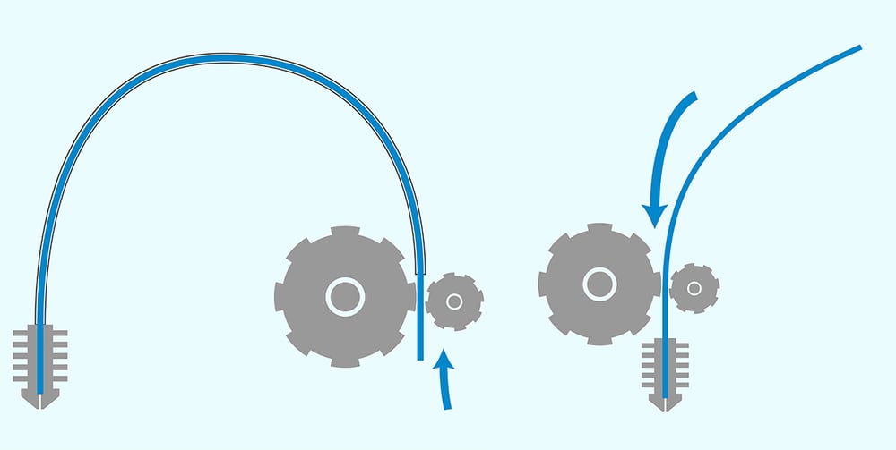
Direct Drive vs Bowden Drive
Most filament 3D printers use either direct or bowden extrusion. Both set-ups use an extruder to push filament through a heated nozzle, either directly or through a bowden tube. Though similar, these extruder formats have major differences. See links below for more information.
Direct Drive Extruder Selection Guide
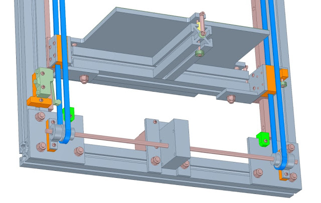
Z-axis design for lifting Build Platform
The current design uses 2 lead screws attached to Nema17 motors ot lift the build platform along with 4 linear rods to constrain movement on XY plane. Other possible design variations for the Z-axis are discussed below. Using two motors to lift the bed can cause problems with synchronization. One option would be to use one motor along with pulleys and a belt to run multiple screws. This solves the problem of syncing.
Discussion 1, Discussion 2 on RepRap Wiki about the optimal number of lead screws, motors and guide rails combination to lift the build platform of a 330x330 cast aluminium build plate. Some of the possible designs are:
-
Original HEVO design by Scott3D of 2 lead screws + 4 12mm linear shafts(rods), run by 2 Nema Motors
-
4 lead screws along with 4 linear shafts on four corners of build platform driven by 1 Nema17 motor and a belt and pulleys.
-
3 lead screws + 2 linear shafts run by pulleys/belt and single Nema17 motor.
-
2 lead screws + 4 linear shafts driven by 1 Nema17 motor with belt and pulleys
- 20 teeth pulley on motor and 40 teeth pulleys on lead screw
- Thingiverse Design from Gavitka and his CAD model on Onshape
-
Single stepper motor with 2 belts on either side to lift bed [design]/https://drmrehorst.blogspot.com/2017/07/ultra-megamax-dominator-z-axis-design_65.html)
Calculating travel on Z - axis
Using 1.8 degree motor with T8x8 four start lead screws gives 8mm travel per rotation with 200 steps (1.8 degree motor) and 400 steps (0.9 degree motor). This is 0.04 mm and 0.02 mm respectively.
All Metal Hotend vs PTFE Lined Hotend
All metal:
- Works well for high (+250ºC) temperatures filaments like nylon or PC.
- No need to replace the PTFE liner (pretty obvious).
- Retraction performs worse.
- Plastic can get stuck to the inner walls. This can lead to clogging, more likely when changing from ABS to PLA (higher temp plastic to lower temp plastic).
PTFE liner hotend:
- Limited working temperature. Above 250 PTFE will start to degrade.
- PTFE tube needs to be replaced more or less often, depending on the use of the printer.
- Retraction performs better.
- Plastic is less likely to get stuck in inner wall (PTFE is very nonstick).
- When using PTFE liner, the plastic is melted very close to the nozzle. Unlike other techniques, in FFF/FDM 3D printing this is more desirable. E.g. to avoid 'heat creep', for a better flow control and more accurate output dimension. Source
Comparison of three popular Nozzles
- Slice Engineering's Mosquito - 165 Euros
- This is a high end well engineered hotend with a copper heat sink and copper alloy heater block.
- Triangle Lab's Dragon - 60 Euros
- The dragon design takes the heater block design from the E3D V6 and the heat sink design from the mosquito and at a price of 60 Euros is the better option of the three. The copper heatsink allows the possibility of a less bulky cooling fan option.
- E3D V6 (Original or Triangle Lab clone) - 15 Euros is the tried and tested E3D design. The heat sink here is however aluminium which has much worse conductivity than copper and so needs much more cooling in an enclosed heated chamber for instance.
Comparison Video from User Nero3DP who has had thousands of hours printing experience with the respective nozzles.
All three print relatively similarly good for the average user if they are correctly calibrated. However, they each have some advantages and disadvantages as listed above.
Best Budget Option is the E3D V4 from trianglelabs which prints perfecttly well but maintainence and nozzle changes are difficult. Plus the heat exchanger is big and cumbersome which needs much more cooling. The design is also heavier than the other two designs. The dragon hotend seems to hit the sweet spot. Both the dragon and E3D V6 will be tested.
Heated Bed Choice
A heated bed helps with layer adhesion in part and prevents warping of the part due to rapid cooling. Moreover, most plastics other than PLA cannot be printed without a heated bed. Even PLA prints much better with a 60degC heated bed. PETG for instance with 70degC and ABS with 110 degC. Firstly one must figure out how much power is required for the specific build plate size and material. The following Online Calculator can be used to calculate time needed to heat an aluminium or glass build plate with heatbed platform of specific size and power. The heated bed is the most power hungry part in a 3D printer build. Therefore the choice of the heated bed directly influences the choice of power supply unit (in terms of power rating).
A solid state relay (SSR) or external MOSFET is often used to switch the bed heater power by connecting its control terminals to the controller board bed heater terminals. An SSR helps by taking the current load away from the controller board and preventing the controller board mosfet from frying, incase of a current surge or high current draw. Make sure that you get the wires to the + and - control terminals of the SSR the right way round.
Caution: when using a high-powered bed heater, in the event that temperature control fails and the bed heater is turned on at full power for an extended period of time, you should either make sure that the bed heater and bed will not exceed a safe temperature, or else install a thermal cutout to disconnect the bed heater or its power supply before excessive temperatures are reached. This is important since if the SSR fails, it fails in the ON-state and this can lead to the heated bed running without interruption. Here the thermal fuse will break power to the heatbed once the temperature of the heatbed exceeds the thermal fuse specific temperature.
There are two ways of heating the heatbed 1. via DC power i.e. through the power supply unit or 2. via mains power supply. Below both ways are described along with precautions required.
Mains voltage AC bed heater
Use a zero-crossing DC-AC SSR such as Crydom D2425, Kudom KSI240D25-L or Fotek SSR-25DA (note: many Fotek SSRs on sale are fakes, using triacs rated at lower current than the marked rating of the SSR). For 230V bed heaters, SSR-10DA may be sufficient. If your bed heater draws more than about 1/4 of its rated current then the SSR may need a heatsink.
Take appropriate safety precautions when using a mains voltage bed heater. In particular:
-
Connect metal parts of the printer to mains ground. This includes the printer frame, the bed plate if it is conductive (e.g. aluminium), and any other metal parts that the bed heater or SSR wiring might come into contact with if wires break.
-
Ensure that it is not possible for the user to touch the SSR terminals or any other exposed mains wiring, or for you to touch the mains wiring when you are working on the printer with power applied. If your SSR is not supplied with a clear plastic safety cover, buy one (for the Crydom SSR listed above, the part number is KS101).
-
If the bed is moving, use highly-flexible wire or cable with a sufficient voltage rating to connect the moving bed heater to the stationary wiring. Cable intended for use in multimeter tests leads is one possibility.
-
If the bed is moving, you must use strain relief at both ends of that cable, to reduce the risk of the cable fracturing with repeated movement.
-
If the bed is moving, use a cable chain or similar to make sure that the cable can't get chafed or trapped.
-
Provide a fuse for the bed heater circuit or the whole printer appropriate to the current draw and the current rating of the mains lead. One option is to use a panel mount IEC mains inlet connector with a switch, neon indicator and fuse built in. See http://www.thingiverse.com/thing:965396 for an example setup on a delta printer. It is highly recommended that you power the printer via a Ground Fault Current Interruptor (GFCI) - more commonly called a RCD (Residual Current Device) in the UK - to protect against electric shock in the event of a fault.
-
Fruitful discussion on Duet website regarding 24v silicon heater vs AC mains silicon heater
The following tutorial video from youtuber Teaching Tech, explains the procedure of installing an AC mains silicon bed heater along with configuring it in Marlin.
Low voltage (12V or 24V) DC bed heater
Use a low voltage drop DC/DC SSR such as the Auber Instruments MGR-1DD80D100 or Crydom DC100D40. The SSR may need a heatsink, depending on the current. Do not be tempted to use a cheap DC-DC SSR such as the SSR-40DD, which is basically useless for this application because of its high voltage drop.
If your heater will reach dangerously high temperatures if it is left on at full power, you should always use a TCO (Thermal cutout) to guard against electronics or firmware failure. The alternative is to choose the heater power carefully so that it is powerful enough to reach the temperatures you want quickly, but not so powerful as to reach a dangerously high temperature when left fully on for a long time.
- use 12AWG wire from PSU > Mosfet and 12AWG Silicon high temp wire from mosfet to heater for DC heater
Choosing Power Supply
Connected Heated bed with Mosfet and power supply 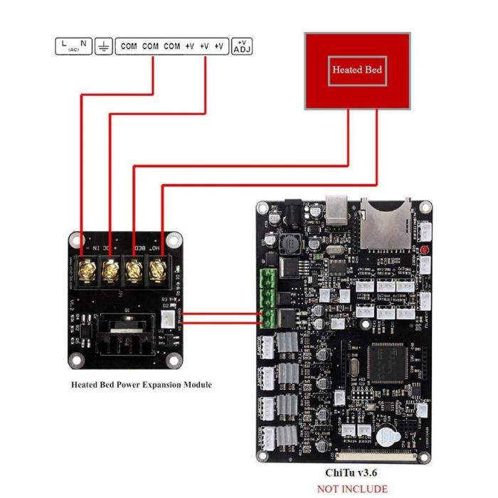
The next most important rating for your 3D printer power supply is output current. As previously stated, this will be the limiting factor for your heated bed and the total number of hot ends you are operating.
The easiest way to calculate how many amps you need is to look at the wattage of the supply, and the rating of your heated bed. Generally, your control board, one hot end, five motors, and a few other electronics (sensors and fans) can be said to use about 100 watts of power. Add in what your heated bed is rated for, and you’ll have a minimum required wattage for your power supply.
To get the amperage, simply divide by the output voltage, e.g. 360W / 12V = 30A.
Here are some examples:
- The standard minimum for 3D printers is usually 240 watts (12 volts @ 20 amps). That would be enough for a printer with a single hot end and a heated bed around 180 x 180 mm.
- With a 200 x 200 mm bed or a second hot end, you’d be better off with 300 watts (12V @ 25A). With both a second hot end and a 200 x 200 mm heated bed, or single extruder with up to a 300 x 300 mm heated bed, 360 watts are standard (12V @ 30A).
- With anything larger than that, a power supply rated upwards of 400W would be recommended. With a 24V PSU, the rules change slightly, as you don’t need quite as much current. Still, we would recommend sticking to the above standard for the best possible operation.
There are two main kinds of power supplies:
ATX PSUs are generally meant for PCs, and while they are manufactured to a higher standard than LED supplies, they require modification to be used with 3D printers. They are also usually more expensive, especially at higher ratings, but incorporate many more safety features, not least of which is closed AC wiring and (usually) a power switch.
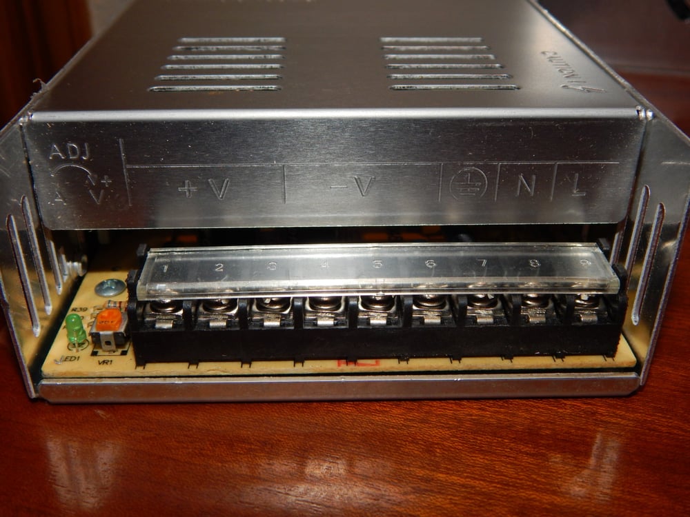
LED PSUs are what you will usually find on a kit like the Anet A8 — that clunky silver box with the really dangerous wiring terminal. These supplies are generally pretty reliable, and they’re cheap and easy to wire. However, there’s no real standard for these supplies to be manufactured to. That means quality will vary a lot based on the seller and manufacturer. The single biggest issue with these supplies is the open AC screw terminals, which are a safety hazard if left uncovered.
The best way to check an LED PSU is with a voltmeter or multimeter. First, wire up your supply to the appropriate power cord, making sure that it is not plugged in while you are handling the wires. When done, plug in your supply, and check the voltage across the output terminals. Be very careful not to touch or short the input AC power terminals.
When checked with a voltmeter, the output should be nearly the same as the indicated output voltage. You may need to fiddle with the small potentiometer next to the screw terminals, as this will change the output regulation slightly. Having the voltage slightly higher will help with an underpowered heated bed, but be careful not to overpower your other components.
Once you know your supply works, wiring it into your printer should be relatively easy. This is especially true with screw terminals and the plug-and-play style setup adopted by most manufacturers. Again, be very sure that you never do any wiring while the supply or the printer is plugged in. Also, be very careful to not touch or short the AC terminals of your PSU while running tests.
If you accidentally touch both AC terminals, or if they short to each other, it’s very easy to electrocute yourself or burn things down. Therefore, to finish up we would recommend you avoid either of these instances by investing the time and filament printing a covering for any exposed wires and terminals. It’s also a good idea to add a switch and a fuse in the process. Example of covering the PSU terminals below.
 https://all3dp.com/2/3d-printer-power-supply-how-to-choose-the-right-one/
3D printer Wiring
One of the most important things about your 3D Printer is the Wiring. If the wire gauge is too small you won’t get enough current to your parts and can even lead to busted cables. Too large of a gauge and you might have a problem fitting those crimped terminals into the connectors. So, the first thing to look for in a wire type is a stranded wire. The reason being your printer will create thousands of cycled movements and if your wire is a solid it will be susceptible to break over the duration of repeated abuse. The stranded wire allows for the cable to flex and move without breaking over time.
A few useful tips: Depending on your level of expertise it may be useful to practice crimping and soldering before wiring everything up. Bad crimps are a major source of problems later on an sometimes hard to identify! Safety Mains cables should be properly dimensioned. Use at least 20 AWG for mains connections, even better would be 18 AWG. Buy a quality SSR, do not source one from china or your house will catch on fire (see Official Sourcing Sheet)! Add a 115-125°C thermofuse to your bed heater as an additional safety measure. Dont run your bed above 105°C, this greatly reduces the lifespan of the adhesive holding it onto the build plate Connect ground to your bed! Connect a ground to your frame!
Connectors The recommended MicroFit 3.0 connectors are specced up to 5A and should be used for all connections to the stepper motors, hotend and limit switches The dupont connectors are used for connections to the RAMPS board Adding molex connectors to all stepper motors is useful. You can disconnect motors while moving the gantry manually to avoid damage to the RAMPS board. Use a 3pin MLX connector (see the official sourcing guide) to allow your bed to be removable without disconnecting from the SSR directly. The thermistor can use a 2pin microfit connector.
Cables The specced silicone wire has been chosen because: It is very high strand count, which means it has higher fatigue life Silicone insulation withstands heat and is more flexible which is good in high movement applications It is less prone to snagging on other wires or the walls inside the cable chain Check you cable loom before installing the tape chains. You need at least: 8x 24AWG wires in the z chain (2 steppers) 4x 24AWG wires in the y chain (endstops) 7x 24AWG (probe, fans, thermistor) 2x 20AWG in the x chain (heater) - do not downsize these, they are oversized for safety reasons SOURCE from VoronDEV website
Instructions on setting up the power connector.

Points to be noted
The hot end and thermister wires are not polarity dependent so the + and - can be plugged in anyway.
3D Printer Wiring Connectors
Dupont Connectors
These connectors work great for RAMPS and Rumba type controller boards with open Pin Headers.

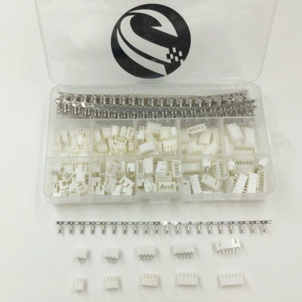
JST Connectors
The JST connectors are what are used on the 32 bi boards such as the MKS, AZteeg etc.
Wiring exmaple of the MKS Sbase V1.3 Board - 
- Great instructable on wiring up the various electronics:
Inserting threaded inserts in Printed Parts
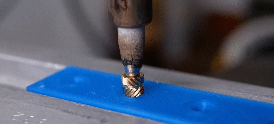
Inserts are put on one end of a 3d printed part whereby the bolt can screw in providing the same functionality as a nut. However since inserts are pressed with heat into the 3d printed part, the hot insert melts the plastic around it and thus forming a very strong bond. Thus inserts have a higher pull out strength than a normal nut that is press fit. Inserts nuts can require precise holes that aren't too small that the nut won't go in and not too big that nut has no plastic to grip on to. When the pull out force is in the direction of which there is no material, the nut could be pulled out when tightening the bolt. This is where a heated insert needs to be used due to its pull out resistance.
Optional Features (Future Work)
- Detect and pause print when filament runs out
- 3D printed design with mechanical roller switch
- Pause print when enclosure door opens
- Wifi connectivity with Rasberry Pi (Octoprint)
Configuring Marlin for MKS Sbase v1.3
The compiling of the Marlin configuration can be done using visual studio. The Platform.io extension in visual studio needs to be installed before that. Platform.io can be used to make changes to the configuration file and upload the compliled firmware/configuraton file to the 3D printer. The latest release of Marlin can be downloaded from Marlin's Github repository. Extract the contents of the zip folder and place the entire folder in the VS workspace.
Open the 'platformio.ini' file in the 'marlin-2.0.x' folder and change the 'default_envs' variable of the default atmel to LPC1768. This is the CPU on the MKS Sbase V1.3, and needs to be defined here. Save and exit the platformio.ini file.
Before You Begin to get your core Configuration.h settings right you’ll need to know the following things about your printer:
- Printer style, such as Cartesian, Delta, CoreXY, or SCARA
- Driver board, such as RAMPS, RUMBA, Teensy, etc.
- Number of extruders
- Steps-per-mm for XYZ axes and extruders (can be tuned later)
- These can be calculated easily using Prusa's Online Calculater
- Endstop positions
- Thermistors and/or thermocouples
- Probes and probing settings
- LCD controller brand and model
- Add-ons and custom components More Information on how to change the configuration according to your setup can be found on Marlin's Configuration page. Source
Next Open the file Configuration.h with the file path - Marlin-2.0.x > Marlin > Configuration.h.
Here the first thing to define is the motherboard used i.e. here after #define MOTHERBOARD enter BOARD_MKS_SBASE as seen in the code snippet below.
- More advanced settings can be found in Configuration_adv.h
Defining Motherboard type
// Choose the name from boards.h that matches your setup #ifndef MOTHERBOARD #define MOTHERBOARD BOARD_MKS_SBASE #endif
Setting Stepper Steps
Considering we are using a GT2 belt of (i.e. distance between two teeth) pitch 2mm and our pulleys have 20 teeth. Therefore distance covered with one full revolution of the 20T pulley will be 40mm. Given that we have 1.8deg stepper motors, i.e. each step of the stepper. This means one full revolution of 360 degrees will be covered in 360deg/(1.8deg) = 200 steps for one full revolution. Considering we have default 1/16 microstepping as default on the MKS Sbase board i.e. each step will be further broken down into 16 steps. This means we will have 16 * 200 = 3200 steps for each revolution.
Calculating Steps/mm = Total Steps / Total distance per Rev = 3200 / 40 = 80 Steps/mm
The value of 80 can be input then for the X and Y steps/mm in Marlin.
For the Z axis we have a lead screw which has a pitch of 8mm and a lead of 8mm. This means each revolution moves the lead screw nut 8 mm. Assuming again 3200 steps per revolution - this gives Steps/mm to be 3200/8 = 400 Steps/mm for Z axis motor.
For the extruder motor, first tryout is with an MK8 extruder fixed to frame (bowden setup), for which this website shows the extruder steps calculation along with assembly steps for the MK8 extruder. This gives the value to be 93 steps/mm which can be further fine tunner by running some tests according to this video
A sherpa mini direct drive extruder which is a fully open source design for a lightweight direct drive extruder, has been ordered which once assembled will be calibrated accordingly and setup on machine. But for now, the MK8 bowden drive will be tested first.
Configuring Extruder Steps
This is a useful video tutorial on how to calibrate or set the extruder steps in Marlin for a bowden drive (MK8 extruder here).
Configuring NPN NO 12mm inductive probe
An inductive probe can be attached to the Z-min Endstop pins in the controller board to use autobed levelling. The 3 inductive probe wires will be attached to the Z-min endstop port which has three pins namely V(voltage), S (Signal) and G (Ground). If the inductive probe is a 5V probe, it can be connected directly to the Z-min Endstop. However, if the NPN NO or NC inductive probe is rated 6-36V or 10-30V (most common), it cannot be connected directly to the Z-min Endstop since the 5V from the Z-min Endstop V pin will not be sufficient to power the probe. The probe will then have to be powered with full 24V from the PSU. Consequently, the output signal from the sensor to board will have the same voltage as the input signal and as our board is rated 24V, it powers the sensor with 24v and therefore the output signal will also have 24v. This could fry the Signal pins on the Z-minstop connector if not reduced since they are rated for a maximum of 5V. This can be fixed in two ways:
- Using a resistor divider setup to reduce the voltage across the G and S pins to be less than 5V.
- Using a transistor
- Using an Optocoupler
The voltage divider setup does not work since the pullup resistors within the MKS Sbase V1.3 board need to be deactivated in the firmware to use the voltage divider. However, this cannot be done through the firmware. The transistor method however works. The following page explains the method to attach the transistor to the NPN NO probe. The user also had no problems making the 18mm inductive probe work with the voltage divider setup but not the 12mm inductive probe.
This is an interesting video describing the setting up of an NPN NO inductive probe and levelling the Z-probe manually using Repetier Host.
Discussion about the use of optocouplers or a transistor to power the NPN probe.
Wiring a mechanical EndStop
The optical endstops that were purchased turned out to be defect i.e. the endstop showed open before any trigger but once triggered, they stay triggered. Only one out of 6 endstops worked normally, the rest all turned out to be defective. So instead a mechanical endstop was wired according to the Simple setup shown to act as the Y axis minimum endstop as shown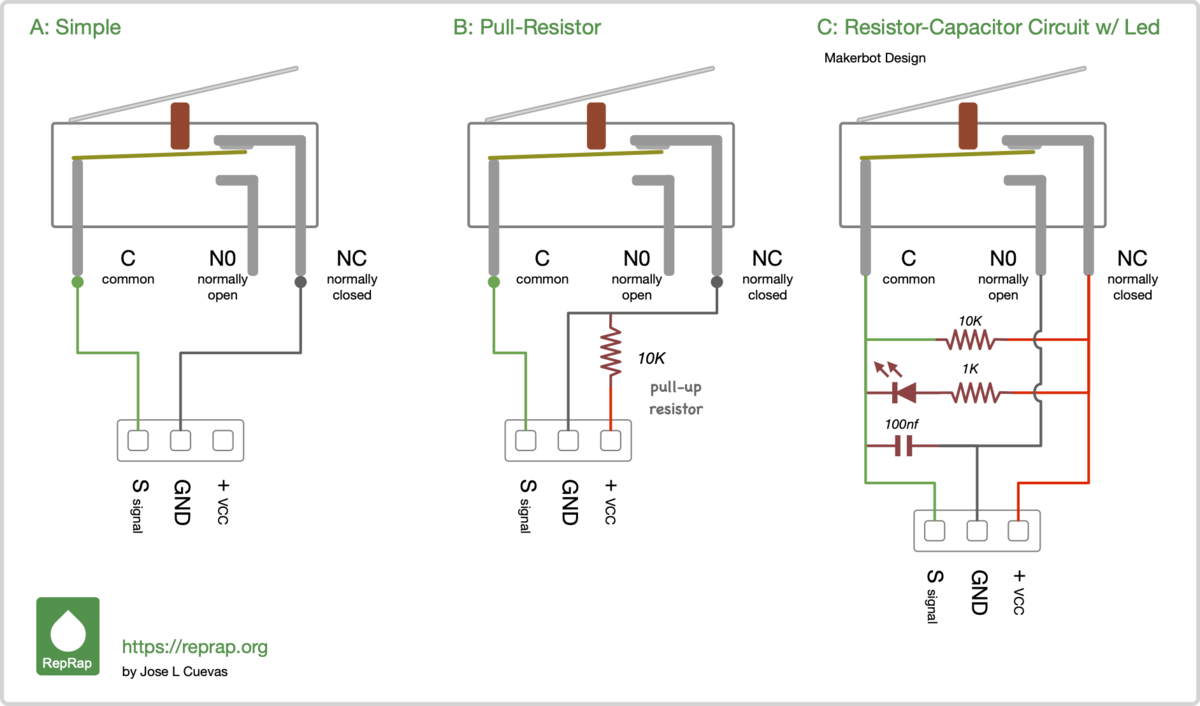 . Whereby the C pin on endstop was connected to signal pin on Y-min Endstop and NC pin was connected to Ground pin on Y-min endstop on controller board. This creates a normally closed Y endstop which is important so that incase the endstop fails, the endstop will be triggered
Tutorial video on connecting a mechanical endstop
Connecting LEDs
Good video explanining different methods to connect LEDs
Setting motor current in Marlin
Motor current can be defined in config_adv.h file whereby the digipot option needs to be enabled. Due to a software bug marlin does not configure. The following fix needs to be made as seen here
Initial Bed Levelling, First Layer Thickness and Z-Offset
Levelling the bed or setting the gap between the nozzle and the bed is done to let the machine know where exactly the bed is. Levelling the bed is crucial to getting a even first layer because it lets the nozzle extrude even across the entire bed. We need both a level build surface and correct nozzle gap to get an even first layer. Then we have the perfect foundation for the rest of our 3D print job. This is usually done with a thin piece of paper being inserted between the nozzle and bed, untill the nozzle just grabs the paper. We are essentially looking to have zero gap between nozzle tip and bed so that the machine can know where exactly Z=0 is i.e. on the bed surface. Understanding the concept of bed levelling and first layer thickness is nicely explained in the following article(https://www.3dmakerengineering.com/blogs/3d-printing/bed-leveling-first-layer-thickness-and-z-offset).
Even though the milled aluminium build plate is flat, it sits on 3D printed brackets and so the bed will not sit on a completely flat plane and will be slightly tilted. Therefore, the build platform needs to be levelled by adjusting the levelling screws. This process is well explained in the following article.
The bed levelling screws were turned 5 full turns to tighten the aluminium build plate mounted on the 4 springs. The bed was heated to 70degC (to let it expand) and after a few ,minutes, the axes were homed and the nozzle was brought manually to the front left corner of the build platform. A thin piece of paper (mine was 0.08mm measured with a Vernier Caliper - the thinner the better) was inserted between nozzle and bed, and the bed levelling screws tightened (tightrning the bed levelling screws compresses the springs and the bed is pulled down towards the bed brackets and distance between nozzle & bed increases) or loosened (distance between nozzle and bed decreases), untill the nozzle just grabbed the piece of paper. The process is repeated on the four corners of the bed i.e. near the four bed levelling screws. Finally it is done in the center of the bed.
Note: For printing PETG use a normal (thin) paper and for printing PLA use a business card (thicker than normal paper). For PETG the first layer needs to be squished slightly more in order to grip the build surface.
Sending print commands
There are 3 ways to print a part from the printer namely:
- via the internal onboard SD card - Here the print job (gcode) can be copied on to the oboard SD card. The on-board SD card is inserted back into the controller board, and the print job (gcode) can be found under the option 'Print from media'. However this is a little cumbersome, since the micro SD card has to be constantly inerted and removed from the controller board.
- via an external SD card connected to an LCD display - Not all LCD display SD card slots work with the MKS Sbase V1.3. Currently the LCD display is a full discount RepRep Smart Controller LCD. This works with a hack that involves turning the EXP connectors on the back of the LCD controller 180 degrees. However, the SD card on the controller does not work without a tricky wire hack. This is mainly a problem with marlin. The REpRAP display SD card works fine with smoothieware. The SD card on the TFT 32 or TFT 28 displays from MKS work with marlin and so next step will be to get one of these.
- directly via the computer using a host software - Repetier host can be used to connect to the printer controller board via the Laptop. A print job can then be uploaded to the SD card by saving the gcode file as XYZ.GCO. This allows then printing from the onboard SD card. The transfer is however slow.
Setting up MKS TFT32 Display
To configure the TFT32 display and install firmware, go to Github repo from Makerbase and download the zip folder for TFT28-32 display.
- Extract the contents
- Open Config folder and copy out the mks_config_EN.txt file and rename it to remove the _EN since that causes problems > file renamed to mks_config.txt
- Go to Firmware > TFT28 32 firmware > Retro > mkstft28.bin
Calibration & Fine Tuning Methods
Printer Calibration cross from thingiverse.
Thingiverse Post of finetuning the CoreXY setup
Instructable on good practices for building 3d printer
A nice way of presenting bill of materials 
Guide on troubleshooting and Calibrating
Problems and Fixes
-
- Problem: Seeing random layer lines on part, layer shifts or even layer seperation
- Cause: Loose Belts
- Solution: Tighten belts till pricking them gives them a slight twang.
Note: Cheap rubber belts can stretch due to the hot atmosphere within an enclosed printer and become loose. This can be first noticed as print lines or layer seperation on part. Tighten bets like before or get genuine GATES belt. Also make sure, the printer enclosure doesn't get too hot by using an exhaust fan on top of printer that will suck out the hot air that has risen to the top.
-
Problem: Stepper motor suddenly very noisy or skipping steps
- Cause: Loose cable ends in JST connectors going to stepper driver ports on controller board
- Solution: Make sure all four wires from stepper motor are properly inserted into the JST connectors
-
Problem: First layer not sticking to bed
-
Cause 1 : Dirty bed (grease, fingerprints, dust etc.)
-
Solution: Clean bed with isopropyl alcohol and dry
-
Cause 2: Z-Offset not set right. Nozzle is too far away from bed i.e. at the Z=0 position there is too large a gap between nozzle and bed.
-
-
Problem: Part cooling fan broke off from Extruder and was being dragged along part
- Cause 1: Pat cooling fan duct too close to hotend heater block, causing it to warp and touch the part while printing.
- Cause 2: Part cooling fan duct slips out of radial fan and hits part
Next Improvements
The surface finish of 3d printed parts is generally good other than some ringing or ghosting that is visible. According to this blogpost(Insert link), this can be attributed to the slack from belts or wobbling idler pulleys. Users have countered these issues in several ways:
- Better quality GT2 belts (gates original)
- Wider belts - for example 9/10mm belts. Current design has 6mm belts.
- 5mm bore idler pulleys instead of current 3mm bore pulleys.
- 5mm smooth shaft for idler pulleys instead of 3mm bolt as shaft in current design
- Precision shim washers between pulleys to act as spacers and reduce play between pulleys
- Put XY motors outside the Printer ENclosure - Check HEVORT's XY Gantry style
Build Instructions
Fabrication
- Printing 3D Printed Parts
- Cutting profiles
- Cutting Enclosure Panels
- Preparing Electronics
- Prepare Wiring
Pre-Assembly
- Build Platform
- Y-Carriage (Left and Right)
- X-carriage
- Extruder Assembly
- X-axis Endstop Assembly
- Exhaust Housing
- Dual Z Mount Pulley Assembly
- Electronics Assembly
- Door Hinges
- Y-axis EndStop Assembly
- X-Y Cable chain assembly
- Power Supply Unit (PSU box) Assembly
- LCD Display with casing assembly
Final Assembly
- Frame
- Left side frame
- Right side Frame
- Left side to right side connection
- Corner brackets installation
- Z-axis lower mounts
- 2.1 M3x25 Bolts (1)
- 2.2 M3 Nut (1)
- 2.3 M5x10 Bolts (2)
- 2.4 M5 Hammernut (2)
- 12mm rods insertion
- Build Platform Installation
- 4.1 2020 Profiles (4)
- 4.2 Corner Brackets 2020 (4)
- 4.3 Z - Axis Bearing Holder (4)
- 4.4 LM12UU Bearings (2)
- 4.5 M5x10 Long Bolts (4)
- 4.6 M5 2020 Hammer Nuts (4)
- 4.7 3mm MK3 Heat Bed (1)
- 4.8 Power Wires (2)
- 4.9 NTC Thermistor (1)
- 4.10 Kapton Tape (1)
- 4.11 3mm Borosilicate Glass Plate (1)
- 4.12 Z Nut Bracket M5x10 Bolts (4)
- 4.12.1 M5 2020 Hammer Nuts (4)
- 4.12.2 Trapezoidal Lead Screw Nuts (1)
- 4.12.3 M3x12 Bolts (4)
- 4.12.4 M3 Nut (4)
- 4.13 Bed Bracket (4)
- 4.13.1 M5x10 Bolts (2)
- 4.13.2 M5 2020 Hammer Nuts (2)
- 4.13.3 M3x40 Bolts with Springs (1)
- 4.13.4 M3 Hand Tightening Nuts (1)
- Z axis upper mounts
- 5.1 M3x25 Bolts (1)
- 5.2 M3 Nut (1)
- 5.3 M5x10 Bolts (2)
- 5.4 M5 Hammernut (2)
- Y-axis Left
- 6.1 XY Stepper Motor Assembly (1)
- 6.1.1 XY Stepper Motor (1)
- 6.1.2 M3x20 Bolts (1)
- 6.1.3 M3x8 Bolts (1)
- 6.1.4 M3x10 Bolts (2)
- 6.1.5 M3 Nuts (1)
- 6.1.6 M5x10 Bolts (3)
- 6.1.7 M5 Hammer Nuts (3)
- 6.1.8 Nema 17 Motor (1)
- 6.1.9 20 Teethed 5 mm Bore Pulley (1)
- 6.2 XY Idler Assembly XY Idler (1)
- 6.2.1 M3x30 Bolts (1)
- 6.2.2 M3x20 Bolts (1)
- 6.2.3 M3 Nuts (2)
- 6.2.4 M5x10 Bolts (2)
- 6.2.5 M5 Hammer Nuts (2)
- 6.2.6 M3 Shim Wahser (4)
- 6.2.7 3mm Bore GT2 Pulleys (2)
- 6.2.8 LM10UU Bearings (1)
- 6.2.9 340mm Wide 10mm Long Smooth Rod (1)
- 6.1 XY Stepper Motor Assembly (1)
- Y-axis Right
- 7.1 XY Stepper Motor Assembly (1)
- 7.1.1 XY Stepper Motor (1)
- 7.1.2 M3x20 Bolts (1)
- 7.1.3 M3x8 Bolts (1)
- 7.1.4 M3x10 Bolts (2)
- 7.1.5 M3 Nuts (1)
- 7.1.6 M5x10 Bolts (3)
- 7.1.7 M5 Hammer Nuts (3)
- 7.1.8 Nema 17 Motor (1)
- 7.1.9 20 Teethed 5 mm Bore Pulley (1)
- 7.2 XY Idler Assembly XY Idler (1)
- 7.2.1 M3x30 Bolts (1)
- 7.2.2 M3x20 Bolts (1)
- 7.2.3 M3 Nuts (2)
- 7.2.4 M5x10 Bolts (2)
- 7.2.5 M5 Hammer Nuts (2)
- 7.2.6 M3 Shim Wahser (4)
- 7.2.7 3mm Bore GT2 Pulleys (2)
- 7.2.8 LM10UU Bearings (1)
- 7.2.9 340mm Wide 10mm Long Smooth Rod (1)
- 7.1 XY Stepper Motor Assembly (1)
- X-axis Assembly
- 8.1 Y Carriage Assembly Y Carriage (2)
- 8.1.1 3mm 20 Teethed Bore Smooth Idler Pulley (1)
- 8.1.2 M3x30 Bolts (2)
- 8.1.3 M3 Nuts (4)
- 8.1.4 M3x40 Bolts (2)
- 8.1.5 M3 Heat Sets Inserts (4)
- 8.1.6 X-End Stop Flag (1)
- 8.2 Y End Stop Flag (1)
- 8.2.1 M3x6 Bolts (1)
- 8.3 Y Carriage Clamps (4)
- 8.3.1 M3x16 Bolts (4)
- 8.4 LMUW10 Bearing (1)
- 8.5 8 mm Rods (2)
- 8.6 X Carriage Assembly X Carriage (1)
- 8.6.1 M3 Heat Sets Inserts (10)
- 8.6.2 LM8UU Bearings (3)
- 8.6.3 M3x14 Bolts (4)
- 8.6.4 Belt Tensioners (4)
- 8.6.5 Belt Clamp (1)
- 8.6.6 Belt Clamp + X Cable Chain Connectors (1)
- 8.6.7 3mm Wide, 12mm Long Double Pins (4)
- 8.1 Y Carriage Assembly Y Carriage (2)
- XY Belt Installations
- 9.1 1.4m Long Belts (2)
- Y Axis End Stop Installation
- 10.1 Endstop Bracket (1)
- 10.2 Endstop Housing (1)
- 10.3 Endstop Cover (1)
- 10.4 Mechanical Endstop (1)
- 10.5 M3x10 Bolts (1)
- 10.6 M5 Hammernut (1)
- 10.7 M3x10 Bolts (1)
- X-Y Cable Chain Installation
- 11.1 X Cable Chain (1)
- 11.2 Y Cable Chain (1)
- 11.3 X-Y Cable Chain Connector Top and Bottom (2)
- 11.4 Y Cable Chain to Frame Connector M3x8 Bolts (2)
- 11.4.1 M3 Nuts (2)
- 11.5 X Cable Chain to Extruder Connector M3 Nuts (2)
- 11.5.1 M3x6 Bolts (2)
- 11.5.2 M3x14 Bolts (2)
- 11.5.3 M3x8 Bolts (1)
- Electronics plate
- PSU Mounting
- Connect Wiring
- Exhaust system
- Enclosure Panels
- Single Motor Z Drive Assembly
- 17.1 Printed Housing (1)
- 17.2 Printed Cover (1)
- 17.3 M3 Nut (4)
- 17.4 Toothless GT2 20T 3 mm Bore Idle Pulley (2)
- 17.5 Toothed GT2 20T 3 mm Bore Idle Pulley (1)
- 17.6 Nema 17 Motor (1)
- 17.7 Toothed GT2 20T Drive Pulley 5 mm Bore (1)
- 17.8 Printed Screw Bolt (1)
- 17.9 M3 Nut (1)
- 17.10 M3x18 (1)
- 17.11 M3x8 Bolt (1)
- 17.12 M3x18 Housing (4)
- 17.13 M3x20 (3)
- Lead Screw with Z Mount Assembly
- 18.1 Z Bottom Bearing Holder Left and Right (2)
- 18.1.1 8 mm Lead Screw (1)
- 18.1.2 Z Bottom Bearing Holder (1)
- 18.1.3 Z Bottom Bearing Nuts (1)
- 18.1.4 608ZZ Bearings (2)
- 18.1.5 GT2 40 Teethed 8mm Bore Pulley (1)
- 18.1.6 M5x10 Bolts (2)
- 18.1.7 M5 Hammer Nuts (2)
- 18.1.8 1100 mm Long, 6mm Wide Closed GT2 Belt (1)
- 18.1 Z Bottom Bearing Holder Left and Right (2)
- Z axis left mounts
- 19.1 M3x25 Bolts (1)
- 19.2 M3 Nut (1)
- 19.3 M5x10 Bolts (2)
- 19.4 M5 Hammernut (2)
- Z axis right mounts
- 20.1 M3x25 Bolts (1)
- 20.2 M3 Nut (1)
- 20.3 M5x10 Bolts (2)
- 20.4 M5 Hammernut (2)