-
Mohammed Omer authoredMohammed Omer authored

Choosing a 3D Printer for the OLSK
The aim of the Open Lab 3D printer is to develop a DIY 3D Printer design that is robust and reliable. It should be possible for anyone to build it, with the posssibility of modifying it according to their budget, requirements and available resources.
Requirements
- The Open lab 3D Printer must be a reliable machine with quality components that can be built from scratch with having to source as few components as possible.
- The printer can be built locally without having to purchase an expensive Kit or fully assembled 3D Printer.
- The printer should make it possible for users to choose their own components for key elements depending on local availability of components and budget.
With quality components and systems being more expensive, 3 designs categories are proposed depending on the user budget. These are namely a high end model, a mid-consumer model and a budget model.
Using MoSCoW method of prioritization to prioritize the design objectives.
- Must have (M) — these are critical and must be included into the product. If even one isn’t included, the release is considered a failure. These can be downgraded if there’s agreement among stakeholders.
- Should have (S) — these requirements are important but not crucial for the release. They’re the first level of “Nice to have”, and generally share the importance of MUST requirements, without being so time-sensitive.
- Could have (C) — these requirements are desirable but not necessary for the release. They’re usually low-cost enhancements to the product. Due to their lower importance, they’re the second level of “Nice to have” features.
- Won’t have (W) — these are considered to be the least-critical or even not aligned with the product strategy. They are to be definitely dropped or to be reconsidered for future releases.
3D Printer Design Goals:
- Enclosed and Stiff construction
- Reliable and repeatable print quality
- As much as possible can be built or sourced locally
- Configurable based on local resources
- No reliance on any manufacturer or proprietary hardware
Technical Specifications
- Build Volume :- 200x200x200 to 400x400x400 (Configurable?)
- Built in Enclosure
- Automatic bed levelling feature with inductive sensor
- Heated Build Platform (> 60 deg C - 110 deg C)
- Good Quality hot end (E3D V6 or clone)
- Use a direct-drive extruder (to print flexible filaments) / Bowden Extruder
- PLA, PETG, ABS and other std. materials
- Detect if filament finishes mid build or gets stuck
- Detect power loss and resume build
- Removable build plate (flex to remove part)
- HEPA Filter with Fan to remove fumes (for ABS printing)
- Emergency Stop Button
- 32 bit control capability
- Linear guides for fast accelerations
- Wifi Connectivity
- IP Cam to see build in real time
Further Requirements (For Workshops)
- Printable assembly and build instruction required.
- SD card, USB drive compatibility and display required.
- Aluminium profile ends needs to be closed with protection pads.
- All holes in profiles, enclosure plates or build plate needs to be drilled and deburred in advance
- Linear bearings needed to lubricated beforehand (or avoided by buying quality bearing like Misumi)
- Threaded inserts (Einpressmutter) needs to be inserted into printed parts before workshop and check possibility to replace inserts with nuts
- Firmware should already be uploaded to controller board with the right settings.
- All cables must be extended to have the right length with insertable JST ends (Workshop will have no soldering activity)
- No sharp corners
- AC wiring completely enclosed.
Design Categories
-
Design 1 High End: (Similar or cheaper than Ultimaker < 2500€ )
- High end 3D printer with profesional grade print quality and speed
- Durable and high end components
- Latest features Possibly look at the Voron V1.8 for this.
-
Design 2 - Mid Consumer (similar in price to Prusa i3 < 800€ )
- Higher end 3D printer with most key advanced features that could be in the price range of the prusa i3
-
Design 3 - Affordable (Similar in price to Ender 3 < 200€ )
- 3D printer that is affordable in the range of the cheapest commercial good quality printer like the popular Creality Ender 3
- This could include similar design considerations in terms of components and mechanics
- Fully DIY so it can be built by anyone and almost anywhere in the world
- Should have all the very basics to allow someone to 3D print good parts
Current 3D Printer Design Log
Frame
For the outer frame of the design, we start with the Hypercube Evoution design by thingyverse user Scott3D which has a boxed construction that has been tried and tested for rigidity and stiffness. The boxed frame is also easier to enclose which is necessary for printing ABS that requires a controlled temperature environment for good layer adhesion. The enclosed frame is also more importantly kids (and pets) friendly. The frame squareness after building can be verified by measuring the opposite diagonals. If they are the same you know have a square structure.
Mechanics
The design uses the CoreXY mechanism whereby the motors for the X and Y axis are fixed to the frame, which makes the X carriage that carries only the print head lighter than a conventional Cartesian design which has to carry the X axis motor. This should allow higher accelerations and printing speed.
CAD 3D Model
Scott3D the original creator of the Hypercube Evolution design has uploaded a parametrized and configurable CAD file in Autodesk Inventor. This needs some modifications since the parameters don't work correctly in the original file. This is a good starting point but later designs will be carried out in Fusion 360 or Freecad. For now a build volume of 300cm3 will be used to build the first iteration.
Part of the design criteria is to fit the power supply and electronics under the base. This means the 3D printer is extended on the bottom by 100 mm but it has a clean look with increased safety by keeping electronics out of reach of (kids). Moreover, transport is easier and the printer can be easily placed on a desk. The printer size is increased on the top by 100mm to accomodate the moving cables of the print head during printing. The final frame size can be adjusted after the first prototype build, considering how space can be optimized within the printer.
Linear Bearings on Smooth rods Comparison
According to this Discussion on difference between various linear bearings
- Bronze bushing - Smooth bearings but could suffer from slip-stick effect if not properly aligned. They also need to be regularly lubricated.
- Linear ball bearings LMXUU (with X for shaft diameter) - Less smoother than bronze bushings but also louder. They are more forgiving of misalignment. They are also less susceptible to wear.
- Igus bearings (special polymer bushing) - similar to bronze bushings and are also susceptible to slip-stick effect.
X-carriage Design
The current X carriage design has a vertically stacked linear rods design with 4 LM8UU bearings on the rods. The spacing between the X carriage rods is 45 mm. On some tests there seems to be some sticking of the bearings. Some users have debated the use of 4 or 3 bearings on the X-carriages. Normally 3 points are sufficient to fix somthing on a plane, and the fourth is over stabilizing. From various posts as well as the reliable Prusa I3 design, the 3 linear bearings seem to be the more tested design.
Discussion on the use of 3 or 4 bearings
Lubricating linear bearings
Linear bearings come packed with just a corrosion inhibiting oil from and not really packed with grease. Therefore the bearings need to be soacked in isopropyl alcohol to wash out all the OEM oil (soak in alcohol for an hour with intermittent swishing). Then let the bearings dry on sheets of paper towel. Apply a grease like Superlube using a 3D printed lubricator fitting from here and end cap from here. Print the grease application fitting from PETG filament with 0.2 resolution and layer width of 0.42. Apply the grease by inserting the printed grease cap into the linear bearings and aligning the slots with the balls and pressing the tube till the grease comes out of the top of the bearing. Then the bearings needs to be slided on the smooth rods multiple times so the rolling of the balls can allow equal grease distributions. Excess grease can be wiped off. Reapply the grease on the bearings and repeat the sliding of the bearings on the smooth rods procedure. This ensures all the balls are sufficiently lubricated. Source
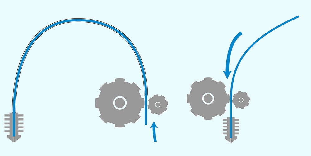
Belts and Pulleys
Most commonly used belts in 3D printers are the GT2 belts which are toothed rubber belts which can have different reinforcing fibes such as steel, fibreglass or just rubber. The GT2 belt is usually 6mm in width and has a pitch of 2 mm. Accordingly the pulleys used are called GT2 pulleys. The size of the pulleys are specified by the inner bore diameter, the number of teeth and if the pulley is a smooth idler, toothed idler or toothed pulley(i.e. no free bearing inside) to connect to a motor for instance. The various forms can be seen below.
6mm wide rubber GT2 belts are used in the design. According to experience for users of CoreXY printers, here belts with steel reinforcement are to be avoided since these are not elastic enough and so can cause wobbling or misalignment of the idlers. Rather fibre reinforced rubber belts are to be used.
- Toothed GT2 Pulley
- Smooth Idler GT2 Pulley
- Toothed Idler GT2 Pulley
Electronics
- Control Board - MKS Sbase V1.3 - 32 bit board
- Mechanical Endstops for X nd Y
- Heat Bed Options
- Silicone Bed Heater
- 220V mains heating
- 24V heating
- MK23 Aluminium Heated bed
- Kapton heater
- PCB Heat bed
- Silicone Bed Heater
- Z-bed levelling sensor choices:
- Induction Sensor
- BL touch
- IR sensor
- Piezo Sensor
Most common Z-bed autolevelling sensors are reviewed and tested in the following video, whereby the most simple and precise seem to be the PINDA 8mm inductive sensor from Prusa and the LJ12A3-4-Z/BX inductive sensor.
Inductive sensors are affordable and precise enough for our application and so we will use a 12mm LJ12A3-4-z/BX inductive sensor. This has a 4mm metal detection distance (for ferrous metal like iron) but for non ferrous metals like aluminium this distance can be halved. So the inductive sensor will have to be placed about 2 mm offset from the nozzle head.
- Rasberry Pi for Octoprint (WiFi printing)
- Fans for cooling electronics
- 60mm Fan for Hepa Filter
- 50mm Duct fan for part cooling
- 30mm Fan for Hotend cooling
Configuring the MKS Sbase V1.3
Direct Drive vs Bowden Drive
Most filament 3D printers use either direct or bowden extrusion. Both set-ups use an extruder to push filament through a heated nozzle, either directly or through a bowden tube. Though similar, these extruder formats have major differences. See links below for more information.
Direct Drive Extruder Selection Guide
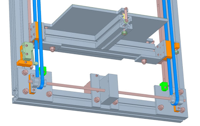
Z-axis design for lifting Build Platform
The current design uses 2 lead screws attached to Nema17 motors ot lift the build platform along with 4 linear rods to constrain movement on XY plane. Other possible design variations for the Z-axis are discussed below. Using two motors to lift the bed can cause problems with synchronization. One option would be to use one motor along with pulleys and a belt to run multiple screws. This solves the problem of syncing.
Discussion 1, Discussion 2 on RepRap Wiki about the optimal number of lead screws, motors and guide rails combination to lift the build platform of a 330x330 cast aluminium build plate. Some of the possible designs are:
-
Original HEVO design by Scott3D of 2 lead screws + 4 12mm linear shafts(rods), run by 2 Nema Motors
-
4 lead screws along with 4 linear shafts on four corners of build platform driven by 1 Nema17 motor and a belt and pulleys.
-
3 lead screws + 2 linear shafts run by pulleys/belt and single Nema17 motor.
-
2 lead screws + 4 linear shafts driven by 1 Nema17 motor with belt and pulleys
- 20 teeth pulley on motor and 40 teeth pulleys on lead screw
- Thingiverse Design from Gavitka and his CAD model on Onshape
-
Single stepper motor with 2 belts on either side to lift bed [design]/https://drmrehorst.blogspot.com/2017/07/ultra-megamax-dominator-z-axis-design_65.html)
Calculating travel on Z - axis
Using 1.8 degree motor with T8x8 four start lead screws gives 8mm travel per rotation with 200 steps (1.8 degree motor) and 400 steps (0.9 degree motor). This is 0.04 mm and 0.02 mm respectively.
Choosing Stepper Motors for the X,Y and Z axes
While choosing the stepper motor for moving the various axes in the 3D printer, several basic calculations can be done to determine the minimum required torque for running the printhead without skipping steps with a specific velocity and acceleration.
Look at the following links for more details on the calculation:
How microstepping reduces motor torque
According to above article microsepping by 1/16 reduces motor torque by 90%, so if the nema 17 motor had a torque of 40Ncm, with 1/16 microstepping only about 4Ncm remains.
Calculating minimum motor torque for X and Y axes
- In a coreXY setup, only the X gantry has to be moved since the Y axes are supported on the frame.
- The X gantry consists of the following parts:
- 2xLM10LUU bearing =
- 2x8mmx370mm long steel rods =
- Extruder Head
- E3D V6 Hotend
- Sherpa Mini Extruder
- Printed parts
- part cooling fan
- Hotend cooling fan
Calculating motor torque for Z axis (Bed platform)
All Metal Hotend vs PTFE Lined Hotend
All metal:
- Works well for high (+250ºC) temperatures filaments like nylon or PC.
- No need to replace the PTFE liner (pretty obvious).
- Retraction performs worse.
- Plastic can get stuck to the inner walls. This can lead to clogging, more likely when changing from ABS to PLA (higher temp plastic to lower temp plastic).
PTFE liner hotend:
- Limited working temperature. Above 250 PTFE will start to degrade.
- PTFE tube needs to be replaced more or less often, depending on the use of the printer.
- Retraction performs better.
- Plastic is less likely to get stuck in inner wall (PTFE is very nonstick).
- When using PTFE liner, the plastic is melted very close to the nozzle. Unlike other techniques, in FFF/FDM 3D printing this is more desirable. E.g. to avoid 'heat creep', for a better flow control and more accurate output dimension. Source
Comparison of three popular Nozzles
- Slice Engineering's Mosquito - 165 Euros
- This is a high end well engineered hotend with a copper heat sink and copper alloy heater block.
- Triangle Lab's Dragon - 60 Euros
- The dragon design takes the heater block design from the E3D V6 and the heat sink design from the mosquito and at a price of 60 Euros is the better option of the three. The copper heatsink allows the possibility of a less bulky cooling fan option. This however will not be used since it seems to infringe on the pending patent by slice engineering mosquito hotend.
- E3D V6 (Original or Triangle Lab clone) is the most popular hotend in the 3d printing market and has been shown to be reliable and made with good precision and quality. The original costs 70 Euros while a good clone from the Trianglelabs costs about 15 Euros. The heat sink here is however aluminium which has worse conductivity than copper and so needs much more cooling in an enclosed heated chamber for instance. Also changing the nozzle required dismounting the entire hotend.
Comparison Video from User Nero3DP who has had thousands of hours printing experience with the respective nozzles.
All three print relatively similarly good for the average user if they are correctly calibrated. However, they each have some advantages and disadvantages as listed above. Best Budget Option is the E3D V6 from trianglelabs which prints perfecttly well but maintainence and nozzle changes are difficult.
Heated Bed Choice
A heated bed helps with layer adhesion in part and prevents warping of the part due to rapid cooling. Moreover, most plastics other than PLA cannot be printed without a heated bed. Even PLA prints much better with a 60degC heated bed. PETG for instance with 70degC and ABS with 110 degC. Firstly one must figure out how much power is required for the specific build plate size and material. The following Online Calculator can be used to calculate time needed to heat an aluminium or glass build plate with heatbed platform of specific size and power. The heated bed is the most power hungry part in a 3D printer build. Therefore the choice of the heated bed directly influences the choice of power supply unit (in terms of power rating).
A solid state relay (SSR) or external MOSFET is often used to switch the bed heater power by connecting its control terminals to the controller board bed heater terminals. An SSR helps by taking the current load away from the controller board and preventing the controller board mosfet from frying, incase of a current surge or high current draw. Make sure that you get the wires to the + and - control terminals of the SSR the right way round.
Caution: when using a high-powered bed heater, in the event that temperature control fails and the bed heater is turned on at full power for an extended period of time, you should either make sure that the bed heater and bed will not exceed a safe temperature, or else install a thermal cutout to disconnect the bed heater or its power supply before excessive temperatures are reached. This is important since if the SSR fails, it fails in the ON-state and this can lead to the heated bed running without interruption. Here the thermal fuse will break power to the heatbed once the temperature of the heatbed exceeds the thermal fuse specific temperature.
There are two ways of heating the heatbed 1. via DC power i.e. through the power supply unit or 2. via mains power supply. Below both ways are described along with precautions required.