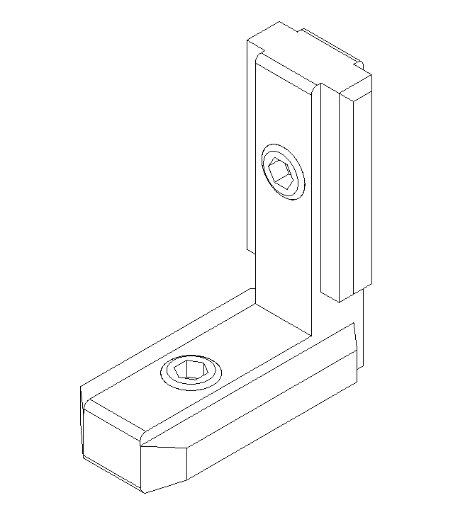
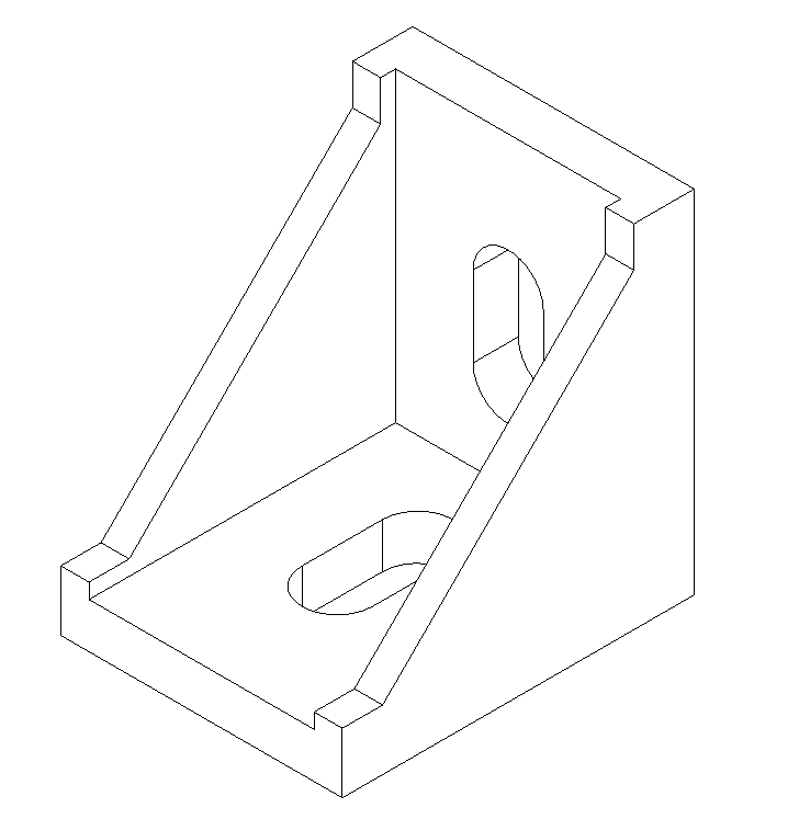
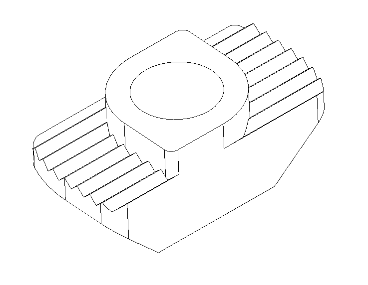
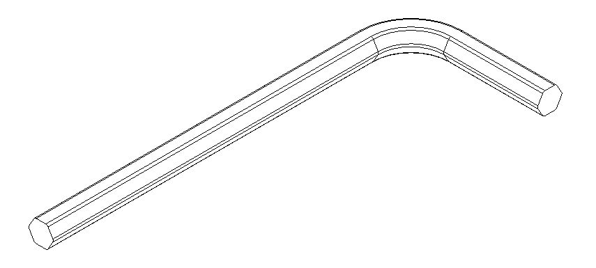
-
Mohammed Omer authoredMohammed Omer authored
Build Instructions
The build instructions below are divided into two parts, namely pre-assembly and final assembly. In the pre-assembly some of the sub-assmeblies or parts are either prepared or assembled together to ease the final assembly. The number in the (#) paranthesis denotes the quantity of the part required. (PA) stands for pre-assembly
Hardware
*** Tools ***
Prepare printed parts
Z-axis lower mounts (2)
Z-axis upper mounts (2)
x
Frame
Z-axis lower mounts
Z-axis linear rods
Build Platform
Z-axis upper mounts
Y-axis Left and Right
X-axis
Parts required
- XY Idler Assembly Left (1)
- XY Stepper Motor Bracket (1)
- Nema 17 Motor (1)
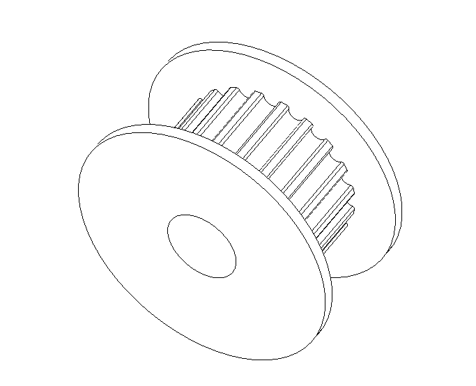
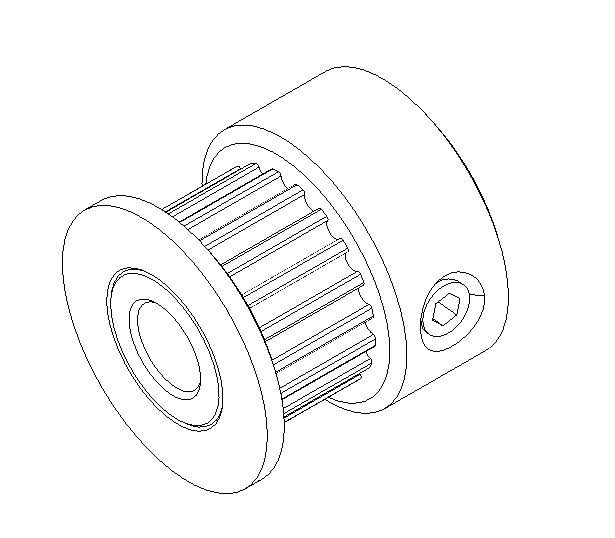
- GT2 20T Drive Pulley (1)
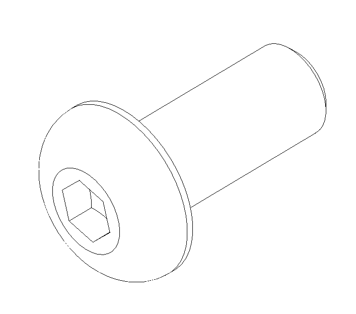
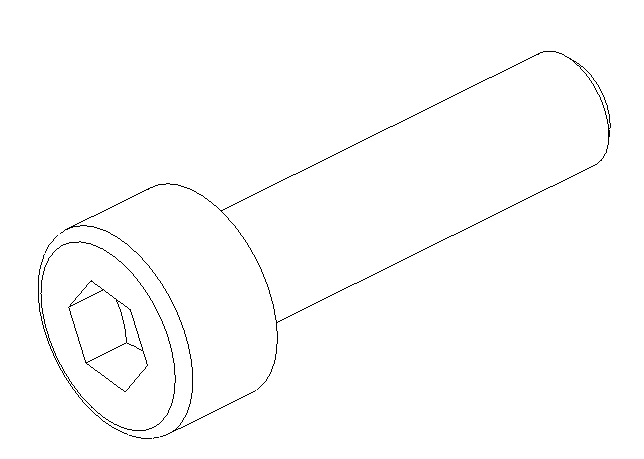
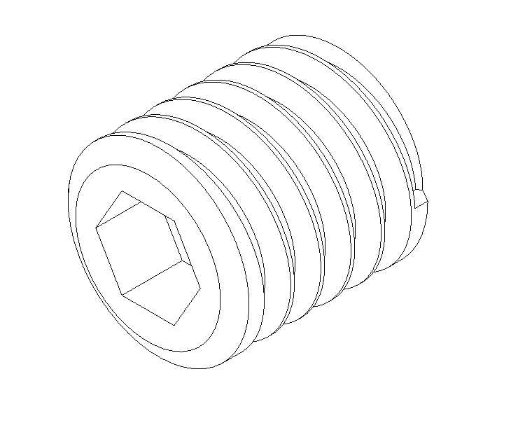
- M3x8mm SHCS (1)
- M3x10mm SHCS (2)
- 10mm dia 340mm long Smooth Rod (1)
- LMW10U Bearing (1)
1. XY Idler Left and Right
Parts required
- XY Idler Assembly Left (1)
- Printed XY Idler - Left (1)
- M3 Nut (2)
- M3x20mm bolt (1)
- M3x30mm bolt (1)
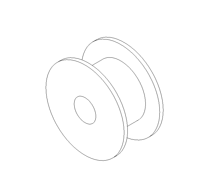
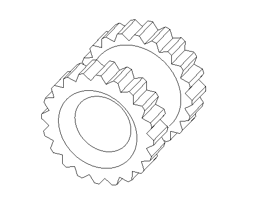
- 3mm Bore GT2 Pulleys (2)
- M3 shim washer (4)
- Tool #2.5 Allen Wrench
- Printed XY Idler - Left (1)
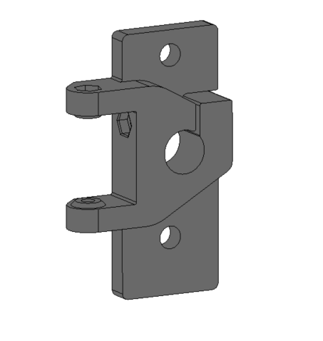
Before and After Assembly
| Before Assembly | After Assembly |
|---|---|
 |
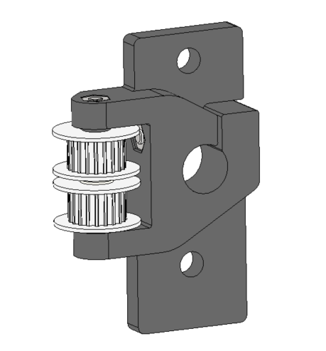 |
Exploded view of XY Idler

Step 0 - Prepare parts required for build
- Printed XY Idler bracket - Left (1)
- M3 Nut (2)
- M3x20mm bolt (1)
- M3x30mm bolt (1)
- 3mm bore GT2 Pulley (2)
- M3 shim washer (4-5)
- Allen wrench #2.5
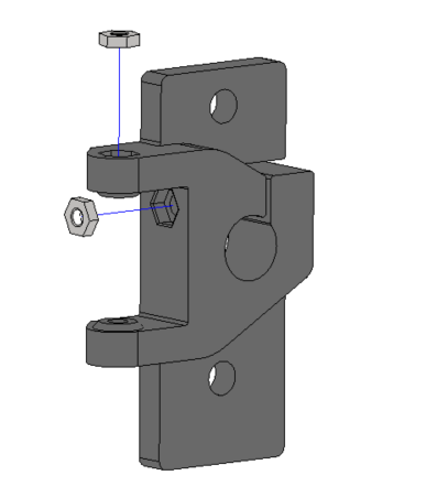
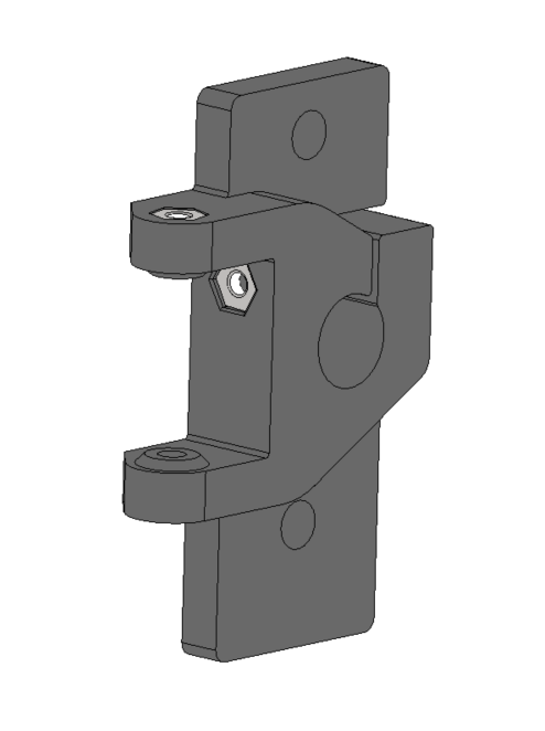
Step 1 - Insert 2x M3 nuts into printed XY Idler bracket
| Step 1 - Insert M3 nuts into slots | Step 1.1 - M3 nuts inserted |
|---|---|
 |
 |
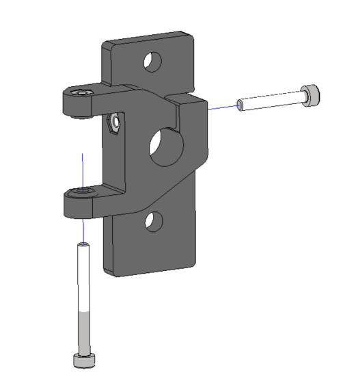
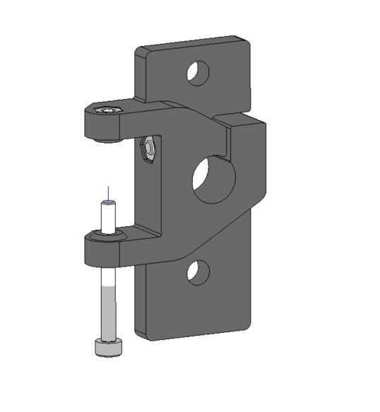
Step 2 - Insert 2x M3 bolts into printed XY Idler bracket
- Insert the M3x20mm bolt till the end but do not tighten now. It will be tightened in a later step when the 10mm smooth rod is inserted
- Insert the M3x30mm bolt only halfway through
| Insert M3 bolts | M3 bolts inserted |
|---|---|
 |
 |
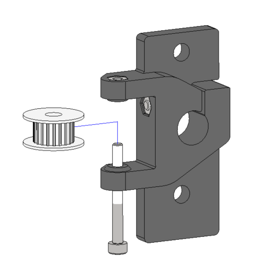
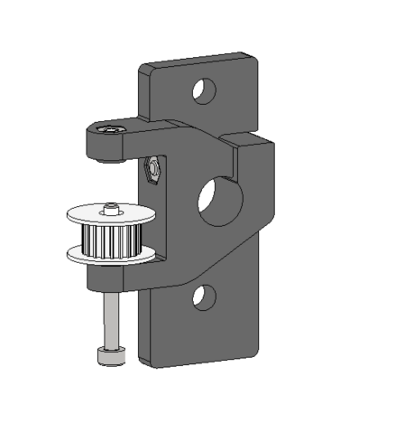
Step 3 - Insert first teethed idler pulley
- The teethed idler has a bore diameter of 3mm and width of 6mm
| Insert Idler pulley | Pulley inserted |
|---|---|
 |
 |
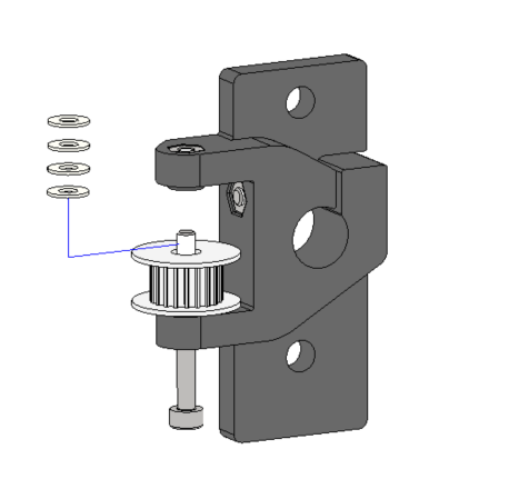
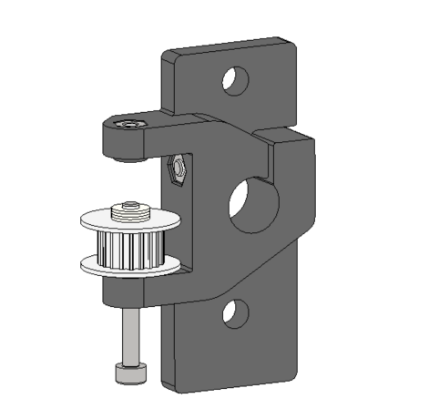
Step 4 - Insert M3 Shim Washers
| Insert 4xM3 shim washers | Washers inserted |
|---|---|
 |
 |
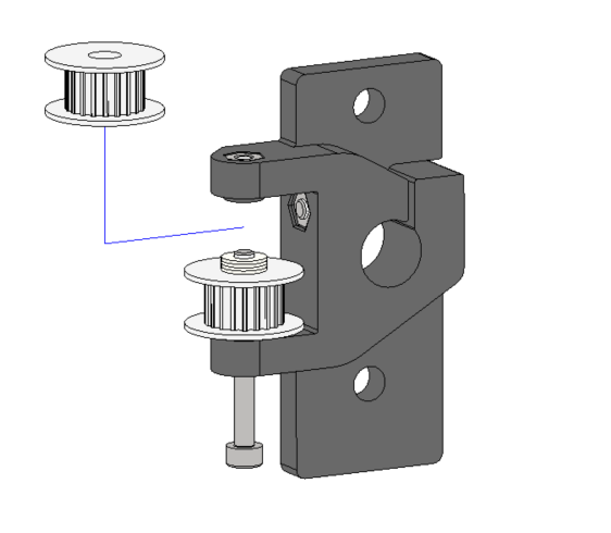
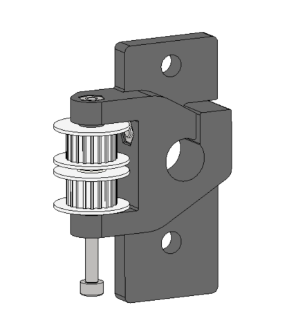
Step 5 - Insert second teethed idler pulley in SHCS
| Insert 2nd teethed idler pulley | Insert M3x30mm SHCS till end |
|---|---|
 |
 |
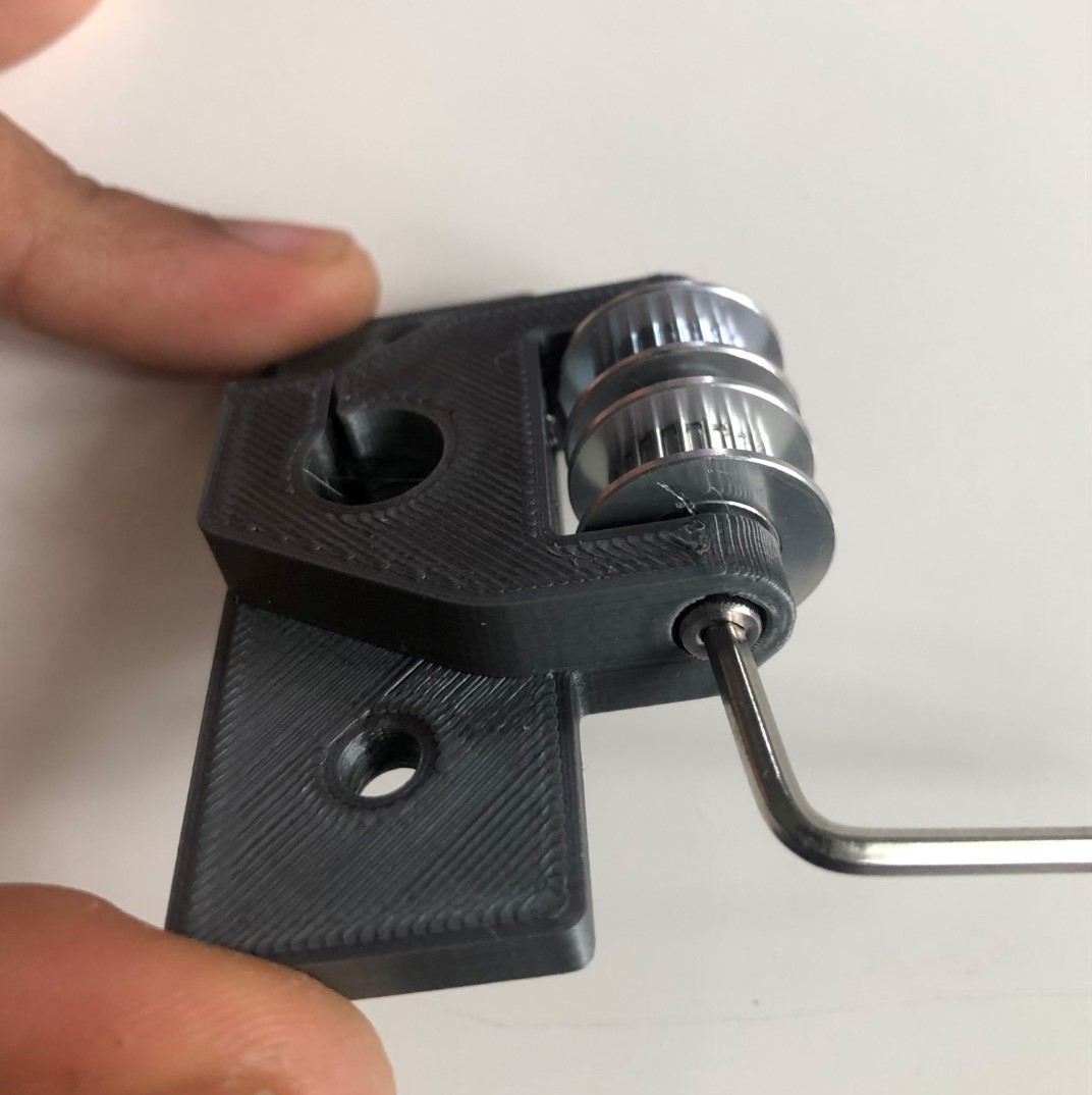
Step 6 - Tighten M3x30mm SHCS
- Screw in and slightly tighten the M3x30mm SHCS with an 2.5mm allen wrench
- Caution! Do not tighten to the point that the pulleys cannot spin freely!
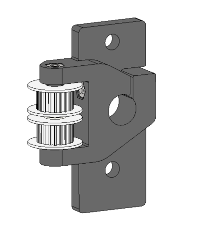
| Tighten Bolt with allen wrench | Finished XY Idler assembly |
|---|---|
 |
 |
Step 7 - Assemble XY Idler Right
The XY Idler Right is a mirror copy of the XY Idler Left asembly. The required components are the same. The only difference is that the XY Idler printer XY Idler Right is a mirrored version of the XY Idler Left.
Repeat steps 0 - 6 for the XY Idler Right assembly
2. XY Stepper Left and Right
Parts required:
- Printed Stepper Motor Bracket - Left (1)
- M3 Nut (1)
- M3x20mm bolt (1)
- Nema 17 Motor (1)
- GT2 20T Teethed 5 mm Bore Drive Pulley (1)
- M3x8mm bolt (1)
- M3x10mm bolt (2)
Exploded view of XY Stepper

Before and After Assembly
| Before Assembly | After Assembly |
|---|---|
 |
 |
Step 1 - Insert M3 nut into printed stepper motor bracket
Step 2 - Insert M3x20mm SHCS but do not tighten so as to deform plastic
Step 3 - Place bracket on Nema17 motor
Step 4 - Insert M3 Bolts and tighten
1.3 Subassembly - Y-axis smooth rod insertion
Parts required:
- 340mm long 10mm dia smooth rod (1)
- Pre-assembled XY Idler Bracket Left
- Pre-asssembled XY Stepper Bracket Left
Step 1 - Insert 10mm dia 340mm long smooth rod into the XY Idler Left and XY Stepper Left
Step 2 - Tighten the M3x20mm SHCS on the XY Idler bracket till the 10mm smooth rod is fixed in place
Step 3 - Tighten the M3x20mm SHCS on the XY Stepper Bracket till the 10mm smooth rod is fixed in place
2. Y-axis Right Pre-assembly (1)
Repeat the same process as in Y-axis pre-aassembly Left. The XY Idler Right and XY Stepper Right are mirrored versions of the XY Idler Left and XY Stepper Left.
3. Build Platform Pre-assembly
Parts Required
- 2020 Profile 335mm long (2)
- 2020 Profile 140mm long (2)
- Printed Corner Brackets (4)
- M5x8mm Bolt (2)
- M5 Hammernut (2)
- Z-Axis Bearing Holder (4)
- M5x10mm Bolt (4)
- M5 2020 Hammer Nuts (4)
- LM8UU Bearing (2)
- Z Nut Bracket (2)
- M5x10 Bolts (4)
- 2020 M5 Hammer Nuts (4)
- Trapezoidal Lead Screw Nuts 8mm (1)
- M3x12 Bolts (4)
- M3 Nut (4)
- Bed Bracket (4)
- M5x10 Bolts (2)
- M5 2020 Hammer Nuts (2)
- M3x40 Bolts with Springs (1)
- M3 Hand Tightening Nuts (1)
4. Z-axis lower mount (2)
Parts required
- M3x25 Bolts (2)
- M3 Nut (2)
- M5x10 Bolts (4)
- M5 Hammernut (4)
5. Z-axis upper mount (2)
Parts required
- M3x25mm bolt (2)
- M3 Nut (2)
- M5x10 Bolts (4)
- M5 Hammernut (4)
6. Y-Carriage Pre-assembly (2)
Parts required
- Y-Carriage Printed Part (1)
- M3 Heatset Insert (4)
- M3 Nut (4)
- M3x14mm bolt (2)
- M3x30mm Bolt (2)
- GT2 20T Teethed 3mm Bore Smooth Idler Pulley (1)
- X-End Stop Flag (1)
Instructions:
- Insert
7. X-carriage Pre-assembly (1)
- Printed X-Carriage (1)
- M3 Heatset Insert (10)
- M3x14mm Bolt (4)
- 3mm dia 12mm long Dowel Pins (4)
- LM8UU Misumi Bearing (3)
8. Extruder Mount Pre-Assembly (1)
- Printed Extruder Mount (1)
- M3 nut (4)
- Insert 2 nuts for extruder motor mount
- Insert 2 nuts for retainer bracket mount
- X-axis Endstop Assembly (1)
- Printed X-endstop holder (1)
- Mechanical micro-endstop switch (1)
- 26G/24G Wire 4cm long (2)
- 2pin JST-XT Female Connector (1)
- M3x6mm bolt (1)
9. Exhaust Pre-assembly (1)
Parts required
- Exhaust Housing (1)
- M3 Heatset insert (7)
- PTFE Tube Through Connector (1)
- 6020 Fan (1)
- M3x12mm bolt (4)
- Exhaust Grill (1)
- Exhaust Mount Bracket (2)
- Carbon Filter (2)
- Fan Mount (1)
